Using an optical see-through display
From ARToolworks support library
Main Page > ARToolKit Professional > Using an optical see-through display
Contents |
About optical see-through AR
ARToolKit uses computer vision techniques for image-based recognition and tracking. Since it uses only a single camera, a self-contained head tracking system can be developed if this camera is fixed to a head mounted display (HMD). In this way AR applications can be developed which use head mounted displays
It is not necessary to have a head mounted display to use the ARToolKit, a camera connected to a computer is the only requirement. Without an HMD ARToolKit applications can be viewed on a computer monitor, with an HMD a more immersive experience can be created.
The ARToolKit programs shown so far have used video see-through augmented reality where the computer graphics are overlaid on video of the real world. This is achieved by using OpenGL to draw the video frame as a background before drawing any other graphics on top. ARToolKit also supports optical see-through augmented reality. In this case an optical see-through HMD is used and only the virtual images are shown in the HMD. Since the HMD is see-through the effect is that the virtual images are overlaid directly on the real world. An example of a see-through HMD is the Virtual iO i-glasses. These are semi-transparent and so can be used for optical see-through AR. Higher end see-though HMDs include the range of displays by Microvision, such as the Nomad.
There are advantages and disadvantages of optical versus video see-through AR. When used with a stereo headset, optical see-through AR allows you to see virtual objects stereoscopically, rather than with bi-occular viewing as with a single camera video see-through system. The real world is also perceived naturally rather than at the resolution of the display. The main drawback with optical see-through AR is the lag in the system. In a video see-through application the video frame of the real world that is shown in the HMD is the same video frame that is used to calculate the head position and orientation so the virtual image will appear exactly overlaid on the real world scene. This is achieved by not showing the video frame until the image processing is completed. However in an optical see-through application the view of the real world cannot be delayed, so the delay introduced into the system by the graphics and image processing is perceived by the user. This results in virtual images that may not appear attached to the real objects they are supposed to be registered with, or that “swim” around. These lag effects are particularly noticeable with rapid head motions or moving the object the virtual image is supposed to be attached to.
For a full discussion of the advantages and disadvantages of optical and video see-through AR, you can refer to Ron Azuma's course notes on Augmented Reality; available on the web at http://www.cs.unc.edu/~azuma/azuma_AR.html
Optical see-through calibration
When using an optical see-thorugh display, In order to achieve good registration of the tracked object with its rendered position in the display it is necessary to measure the exact position of the of the user’s eye relative to the head worn camera. This is achieved by a simple self-calibration method in which the user holds a calibration pattern in front of the eye and lines up the pattern with a virtual cross hair shown in the see-through display. To achieve good optical see-through viewing, eye position calibration should be done each time a user starts the AR application.
Calibration for stereo optical displays
Although the procedure below is written for a monocular display, optical see-through calibration is especially important when using a stereo display. Any registration error (any offset in position between the real world object and its viewed position in the display) will be much more obvious when viewing stereoscopically, and will be perceived as error in depth. Calibration for stereo proceeds exactly as below, but should be conducted for each eye in turn, i.e. should be run first for one eye with the other closed, and then vice-versa.
The calibration pattern
The calibration pattern used is shown below, and can be found in the pdf file Optical calibration pattern.pdf in the patterns folder inside the doc folder in your ARToolKit distribution.This should be printed out and mounted on a piece of cardboard with enough white space around it so that it can be easily held in one hand. Note that the length of each side of black square of the calibration pattern must be exactly 80mm.Running calib_optical
Prior to calibrating for the user’s eye position, it is necessary to calibrate for the optical properties of the camera. The method for doing this is detailed in the section Calibrating your camera.
The calib_optical utility program contains code for calibration so using this as an example the calibration steps are as follows:
- Place the HMD firmly on your head.
- While calib_optical is running press the space bar. A white cross should appear on-screen.
- If you need to see the video-image (temporarily, e.g. to see if the camera is correctly focussed or has correct brightness or contrast) press the "o" key. While in this mode, you can press "d" to see the debug (binarized image) and "-" and "+" to adjust the binarization threshhold to get nice black and white borders on the pattern.
- Looking only through the eye being calibrated (i.e. with the other closed or covered), hold the calibration card in your hand at arms length and use your other hand to press the spacebar when required.
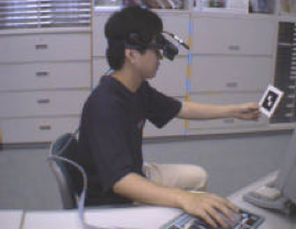 A user performing optical calibration by lining up their eye position with the pattern
 - Move the calibration card until a red or green square appears at the intersection of the white cross hairs. This means that the calibration card is in view of the head mounted camera and it’s pattern has been recognized.
- Keeping the unused eye shut and the red or green square active move the calibration card and move your head to line up the white cross hairs with the intersection of the squares on the card.
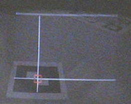 View in headset during optical calibration procedure
 - Press the space bar. If the calibration parameters are captured the red or green square will change to the opposite color.
- Keeping the unused eye shut, move the calibration card as close as possible to your viewpoint while keeping the red or green square active and repeat steps 5 and 6.
- After capturing a calibration point at arms length and close to the body, the cross hairs should change position – keeping your right eye shut repeat steps 3 through 7. There are 5 calibration positions so ten measurements are taken in total for one eye.
After taking ten measurements, the white cross hairs will disappear and the calibrated eye position will be printed out, looking something like this:
At this point you will be prompted for the name of the file in which to save the calibration results.
$: ~/ARToolKit4/bin >./calib_opticalCamera image size (x,y) = (640,480)
Reading camera parameters from Data/camera_para.dat (distortion function version 3).
*** Camera Parameter ***
--------------------------------------
SIZE = 640, 480
Distortion factor = 311.500000 226.000000 1.006924 1.000000 11.000000 4.400000
804.38635 0.00000 312.50000 0.00000
0.00000 803.87536 239.00000 0.00000
0.00000 0.00000 1.00000 0.00000
--------------------------------------
ProcMode (X)   : FRAME IMAGE
DrawMode (C)   : TEXTURE MAPPING (FULL RESOLUTION)
TemplateMatchingMode (M)   : Color Template
Window was resized to 640x480. Camera image of 640x480 will be scaled by 1.000000 (h) and 1.000000 (v).
CTYPE = 2vuy
Beginning optical see-through calibration.
Position 1 (far) captured.
-- 3D position -115.184635, 57.446030, 564.060060.
-- 2D position 160.000000, 120.000000.
Position 1 (near) captured.
-- 3D position -103.269729, 60.947248, 410.983793.
-- 2D position 160.000000, 120.000000.
Position 2 (far) captured.
-- 3D position 55.854849, 60.853172, 547.750355.
-- 2D position 480.000000, 120.000000.
Position 2 (near) captured.
-- 3D position 21.727804, 60.089365, 391.802531.
-- 2D position 480.000000, 120.000000.
Position 3 (far) captured.
-- 3D position -27.638938, -10.452357, 562.451288.
-- 2D position 320.000000, 240.000000.
Position 3 (near) captured.
-- 3D position -48.164517, 28.288982, 297.542144.
-- 2D position 320.000000, 240.000000.
Position 4 (far) captured.
-- 3D position -110.804220, -80.708711, 567.940307.
-- 2D position 160.000000, 360.000000.
Position 4 (near) captured.
-- 3D position -96.756636, -22.429633, 361.695711.
-- 2D position 160.000000, 360.000000.
Position 5 (far) captured.
-- 3D position 61.444556, -77.380158, 556.955252.
-- 2D position 480.000000, 360.000000.
Position 5 (near) captured.
-- 3D position 42.332470, -56.220412, 461.777917.
-- 2D position 480.000000, 360.000000.
Expressed relative to camera axes, eye is -70.561950 mm to the right, -70.495486 mm above, and 30.678455 mm behind the camera.
Eyepoint error is 124.106253.
--------------------------------------
Field-of-view vertical, horizontal = 27.056970, 32.055244 degrees, aspect ratio = 1.184731
Transformation (eye to camera) =
0.98718 -0.14631 0.05781 -70.56195
0.15453 0.96684 -0.11723 -70.49549
-0.03987 0.12466 0.97706 30.67845
0.00000 0.00000 0.00000 1.00000
--------------------------------------
Optical display parameters and eye to camera transformation matrix saved to file optical_param.dat.
You will note that a measurement of the calibration error is generated. The lower this value, the more accurate your calibration was.
At this point you will want to move the newly-generated calibraton file into the Data/ directory, and then test it. Read on..
Stereo optical see-through calibration
If using stereo, switch eyes and repeat steps 3 through 8 to capture ten measurements for the other eye.
Using the calibration results
Monocular see-through
ARToolKit for Desktop
The application 'optical' is an example demonstrating monocular optical see-through with a calibrated camera and display.
- It expects to load calibrated camera parameters from the file Data/camera_para.dat and calibrated optical see-through parameters from the file Data/optical_param.dat, so be sure that you have run the calibration programs (calib_camera and calib_optical) and moved the results of your calibration into the Data directory.
- Print out the Hiro and Kanji markers and make sure that they are exactly 80mm on each side. (Unlike video-see through where a marker of incorrect size will still be overlaid with the content, in optical see-through, the axis of the camera and the axis of the display do not usually align, and so a mis-sized marker will result in radically incorrect display).
- Run 'optical'.
The screen will initially be blank, as the application is in optical see-through mode. You can press the "o" key to see the camera image temporarily, if (for example) you need to adjust the camera focus. While showing the camera image you can use the standard set of keys "d" to toggle display of the debug image and "-" and "+" keys to adjust the tracking threshhold. Press "o" again to go back to optical mode.
When the Hiro marker is held in the field of view of the camera and display, you should see the OSG "axes" model overlaid on top of the marker. If your calibration was accurate the two should be quite well aligned (registered). If your calibration was poor, you will observe position and orientation offsets between the cube and the marker, and the 3D objects may appear to float above or below the cards or may be distorted. The same will apply if the camera has moved relative to the display since it was calibrated, or if the display has moved on your head, or if someone is using the application when it has been calibrated for another person’s eyes.
Although the calibration process may appear quite time consuming, with practice it can be completed in just a couple of minutes and should produce good optical viewing results.
Usage: ./optical [options]
Options:
  --vconf <video parameter for the camera>
  --cpara <camera parameter file for the camera>
  -cpara=<camera parameter file for the camera>
  --width w     Use display/window width of w pixels.
  --height h    Use display/window height of h pixels.
  --refresh f   Use display refresh rate of f Hz.
  --windowed    Display in window, rather than fullscreen.
  --fullscreen  Display fullscreen, rather than in window.
  -h -help --help: show this message
If you want to change the markers, you can edit the file Data/markers.dat. If you want to change the content, edit the file Data/objects.dat.
ARToolKit for Unity
To use the optical calibration results in ARToolKit for Unity, the parameters file must be renamed and moved into the correct location inside your Unity project. The correct location is inside a folder at path Assets/Resources/ardata/optical inside your Unity project. The file name must end with the suffix ".bytes", so if (for example) your parameters file is named "optical_param.dat", rename it to "optical_param.bytes" and drop it into this folder. The first part of the filename can be named to help you identify the parameters.
Once the parameters file is in this location, optical mode should be enabled in the "ARCamera" component in your Unity project. A popup will show a list of all available ".bytes" files in the Assets/Resources/ardata/optical folder. Select the preferred parameters file.
By default, when using optical mode, the video background is initially turned off. If you want to see the video image, press [Enter] (desktop platforms) or [Menu] (Android) and use the on-screen control to toggle the video background on or off.
Stereo see-through
ARToolKit for Desktop
The application 'opticalStereo' is an example demonstrating stereo optical see-through with a calibrated camera and display.
- It expects to load calibrated camera parameters from the file Data/camera_para.dat and calibrated optical see-through parameters from the files Data/optical_param_left.dat and Data/optical_param_right.dat, so be sure that you have run the calibration programs (calib_camera and calib_optical) and moved the results of your calibration into the Data directory.
- Print out the Hiro and Kanji markers and make sure that they are exactly 80mm on each side. (Unlike video-see through where a marker of incorrect size will still be overlaid with the content, in optical see-through, the axis of the camera and the axis of the display do not usually align, and so a mis-sized marker will result in radically incorrect display).
- Run 'opticalStereo'.
Usage: ./opticalStereo [options]
Options:
  --vconf <video parameter for the camera>
  --cpara <camera parameter file for the camera>
  -cpara=<camera parameter file for the camera>
  --width w     Use display/window width of w pixels.
  --height h    Use display/window height of h pixels.
  --refresh f   Use display refresh rate of f Hz.
  --windowed    Display in window, rather than fullscreen.
  --fullscreen  Display fullscreen, rather than in window.
  --stereo [INACTIVE|DUAL_OUTPUT|QUADBUFFERED|FRAME_SEQUENTIAL|
            SIDE_BY_SIDE|OVER_UNDER|HALF_SIDE_BY_SIDE|
            OVER_UNDER_HALF_HEIGHT|ANAGLYPH_RED_BLUE|ANAGLYPH_RED_GREEN
            ROW_INTERLACED|COLUMN_INTERLACED|CHECKERBOARD].
            Select mono or stereo mode. (Not all modes supported).
  -h -help --help: show this message
ARToolKit for Unity
ARToolKit for Unity v5.1.2 and later support stereo optical see-through. At present, only half-width side-by-side stereo mode is supported, as used in e.g. the Epson Moverio BT-200 display. An example scene named “StereoOpticalScene” is included in Assets/Example Scenes folder. It displays how to set up a project for stereo optical.
As with mono optical see-through in Unity (see above), to use the optical calibration results in ARToolKit for Unity, the parameters file must be renamed and moved into the correct location inside your Unity project. The correct location is inside a folder at path Assets/Resources/ardata/optical inside your Unity project. The file name must end with the suffix ".bytes", so if (for example) your parameters files are named "optical_param_left.dat" and "optical_param_right.dat", rename them to "optical_param_left.bytes" and "optical_param_right.bytes" and drop them into this folder.
Stereo optical see-through is set up in Unity by taking an existing Camera object with an ARCamera script attached, and duplicating it (in the Unity Editor, select the Camera game object, then choose "Edit->Duplicate" from the menu bar). You can rename the cameras to make clear which camera corresponds to which eye, as in this example:
On each camera, tick the boxes “Part of a stereo pair” and “Optical see-through mode”. On the desired “left” camera, choose “Stereo eye: left” and select the calibrated optical parameters file for the left eye from the "Optical parameters file" popup. Repeat step 4 for the right eye.
Alternative stereo configuration
ARToolKit for Unity v5.1.3 and later also support an alternative configuration for stereo optical see-through which may suit some users. In this alternative, optical calibration is performed only for one eye, and then this value is used for both eyes with a manual "offset" value applied to the second eye. This arrangement is better when the distance between the eyes can be accurately estimated. You might wish to use the adult-population average eye separation of 0.065 metres (65 millimetres, or 2.56 inches).
To set up in this way, set up as above, but choose the same "Optical parameters file" popup for both left and right eyes. Then, if the optical calibration is for the right eye, enter a negative value in the box labelled "Lateral offset right" for the left eye camera, e.g. -0.065. If the optical calibration file is for the left eye, enter a positive value in the box for the right eye camera, e.g. 0.065.
A word on limitations of optical see-through
While optical see-through AR is an attractive ideal, in practice it is very difficult to achieve accurate registration with optical see-through AR systems. (Registration is the alignment of the virtual objects shown in the display and their real-world referent). This owes not so much to the limitations of calibration procedures, but to the nature of optical see-through display.
Optical see-through calibration depends on accurately knowing the precise relationship of two optical apertures: the iris of the camera imaging the scene, and the iris of the eye of the user viewing the scene. We can estimate the relationship between the two by measuring the distance between the display being used to produce the imagery and the lens of the camera, but the position of the iris of the eye of the user and the display is not fixed. We can attempt to control this relationship by fixing the display very tightly in place on the user's head, but its position will differ by small amounts between sessions and between users. Even when accurate calibration has been achieved, a tiny shift in the position of the display relative to the user's eye can produce a significant offset in registration of objects in the scene. Unless using a headset which includes eye-tracking, accuracy of registration is limited.
Of course, alignment between virtual and real objects is desirable for video see-through too, but in video see-through the users sees the virtual objects overlaid on the source image being used for tracking. There is minimal registration error between the video stream and the overlaid objects, and the misalignment of the video stream and the real scene behind and around it is much less noticeable to the user. This is one of the key reasons why video see-through display has become so widely used in AR research.